ta Modeling Using Entity-Relationship ModelSummary: Conceptual modeling is an important phase in the database design process. In this lecture, we will discuss brieftly about data modeling and then focus on modeling concepts of the Entity – Relationship Model, which is popular high-level conceptual data model.
Database Application Development ProcessDatabase Application Development is the process of obtain real-world requirements, analyse requirement, design the data and functions of the system and then implement the operations in the system.
The figure below shows the main phases of the database application development process.

Figure 1: The main phases of the database application development process
As we can see, the first step is Requirement Collection and Analysis. During this step, the database designers have to interview the customers (database users) to understand the be-built system, obtain and document the data and functional requirements. The results of this step is a document including the detail requirements of the users.
Data Modeling is the next step in the process. This step is sometimes considered as a high-level and abstract design phase (conceptual design). The aims of this phase are:
* Describes what data is contained in the database (E.g entities: students, lecturers, courses, subjects etc.)
* Describes the relationships between data items (E.g Students are supervised by Lecturers; Lecturers teach Courses )
* Describes the constraints on data (E.g Student Number has exact 8 digits; A subject has 4 or 6 unit of credits only)
The data items, the relationships and constraints all are expressed using the concepts provided by the high-level data model. Because these concepts donot include the implementation details so the results of the data modeling process is a (semi) formal representation of the database structure. This result is quite easy to understand so it is used as reference to make sure that all the user’s requirements are met.
The third step is Database Design. During this step, we might have two substeps called Database Logical Design which define a database in a data model of a specific DBMS and Database Physical Design which define the internal database storage structure , file organization or indexing techniques. The last two steps shown are Database Implementation and Operations/Interfaces Building focus on create instance of schema and implementing operations and user interfaces.
In the database design phases, data is represented using a certain data model. Data Model is a collections of conceptual concepts or notations for describing data , data relationships, data semantics and data constraints. Most data models also include a set of basic operations for manipulating data in the database.
As mentioned in the first lecture, data models are either:
1. Conceptual models
* Database is considered as a collection of entities (objects) of various kinds.
* These model provide a flexible data structuring capabilities.
* The typical examples of this model is entity-relationship model, object-oriented model or semantic data model.
2. Record based logical models
* Database is considered as a collection of fixed – size record.
* These models are closer to the physical level or file structure so they are easier to implement.
* The three most wellknown models of this kind are relational data model , network data model or hierachical data model.
3. Physical models
* Provide concepts that describe the details of how data is stored in the computer’s memory
In the next section, we will discuss the Entity-Relationship Data Model in more detail.
Entity Relationship Model (ER Model)Entity Relationship Data Model has existed for 30 years (original description: Chen, ACM Transactions on Database Systems, 1(1), 1976).
The ER model is wellsuited to data modelling for use with databases because it is fairly abstract and is easy to discuss and explain. ER models are readily translated to relations.
ER modelling is based on two concepts:
* Entities, that is, things. Eg. Prof. Ba, Course Database Sytem
* Relationships, that is, associations or interactions between entities. Eg. Prof. Ba teachs course Database Sytems
ER models (or ER schemas) are represented by ER diagrams.
The example database In this lecture, we will use a sample database called the COMPANY database to illustrate the concepts of Entity Relationship Model. This database contains the information about employees, departments and projects:
* There are several departments in the company. Each department has an unique identification, a name, location of the office and a particular employee who manages the department.
* A department controls a number of projects, each of which has unique name, a unique number and the budget.
* Each employee has name, an identification number, address, salary, birthdate. An employee is assigned to one department but can join in several projects. We need to record the start date of the employee in each project. We also need to know the direct supervisor of each employee.
* We want to keep track of the dependents of the employees. Each dependent has name, birthdate and relationship with the employee.
Entity, Entity Set and Entity TypeEntity is an object in the real world with an independent existence and can be differentiated with other object
An entity might be
* Object with physical existence. Eg a lecturer, a student, a car
* Object with conceptual existence. Eg a course, a job, a position
An Entity Type defines a collection of similar entities
An Entity Set is a collection of entities of an entity type at a point of time. In ER diagram, an entity type is represented by a name in a box

Figure 2: Entity type in ER diagram
AttributesEach entity is described by a set of attributes that model “properties of interest”
E.g. Employee = (Name, Address, Age, Salary)
Each attribute has a name, associate with an entity and is associated with a domain of legal values. However the information about attribute domain is not presented on the ER diagram
In the diagram, each attribute is represented by an oval with a name inside.
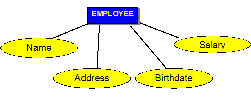
Figure 3: Attribute diagram
Types of Attributes
* SIMPLE attributes are attributes that are drawn from the atomic value domains
E.g. Name = {John} ; Age = {23}
* COMPOSITE attributes: Attributes that consist of a hierarchy of attributes
E.g. Address may consists of “Number”, “Street” and “Suburb” → Address = {59 ‘Meek Street’ ‘Kingsford’}
* SINGLE VALUED attributes: Attributes that have only one value for each entity
E.g. Name, Age for EMPLOYEE
* MULTIVALUED attributes: Attributes that have a set of values for each entity
E.g. Degrees of a person: ‘ BSc’ , ‘MIT’, ‘PhD’
* DERIVED attributes: Attributes Contain values that are calculated from other attributes
Eg. Age can be derived from attribute DateOfBirth. In this situation, DateOfBirth might be called Stored Attribute.

Figure 4: Notation of Composite attribute in ER Diagram

Figure 5: Notation of Multivalued attribute in ER Diagram

Figure 6: Notation of Derived attribute in ER Diargam
KeysAn important constraint on the entities is the key. Key is an attribute or a group of attributes whose values can be used to uniquely identify individual entity in an entity set.
For example, for the entity EMPLOYEE = {EID, Name, Address, Age, Salary}
* Definite keys are any set that involving EID
* Possible keys might be {Name, Address}
* Unlikely keys: {Name}, {Age}
There is a key that is chosen by the database designer used as an identifying mechanism for the whole entity set: primary key. This key is indicated by underlying attributes in the ER model.

Figure 7: Key Notation
Relationship, Relationship Set and Relationship Type
* Relationship is an association among several entities
Eg. Employee (John) joins Project (Netlife)
* The set of similar associations at a point of time is called the Relationship Set
Eg. the following “Joins in ” is a relationship set
Employee (John) joins in Project (Netlife)
Employee (Mark) joins in Project (GreenNet)
Employee (Sara) joins in Project (mFORM)
Employee (Steve) joins in Project (Netlife)
* Relationship type is a collection of relationships among entities from a certain set of Entity Types
We can define the relationship type more formally.
Definition: Consider n ≥ 2 possibly non-distinct entity types E1, E2, …, En.
A relationship is a tuple(e1, e2,…, en) is a subset of E1 x E2 x … x En.
A relationship type R is a subset of the Cartesian Product E1 x E2 x … x En.
R has degree n
In the ER diagram, relationship type is represented by a diamond with a name inside and connects by straight line to the rectangles representing entity type.

Figure 8: Relationship type notation
Degree of Relationship Type
The degree of a relationship type is the number of participating entyties types.
* Unary (Recursive) relationship type is the relationship that involve only one entity type. However, the same entity type participates in a relationship type in different roles. For example, figure below shows the Supervise relationship type which relates an Employee and a Supervisor who is also an employee. So in this relationship, one employee has the role of supervisor, another has the role of supervisee.

Figure 9: Supervise Relationship
In ER model, we have the diagram

Figure 10: Supervisor Notation
* Binary relationship type: This relationship type has two entity types link together. This is the most common relationship.
For example the “Joins in” relationship between EMPLOYEE and PROJECT

Figure 11: "Joins in" Relationship
The ER diagram for this relationship type is :

Figure 12: "Joins in" relationship notation
* Ternary relationship type: If there are three entity types link together, the relationship is called ternary relationship.
For example: The Supply relationship associates a SUPPLIER, a PART and a PROJECT.

Figure 13: Ternary relationship example
The ER diagram for this relationship type is:

Figure 14: Ternary relationship notation
 ليتك تحلو والحياة مريره وليتك ترضى والانام غضاب
وليت الذى بينى وبينك عامر وبينى وبين العالمين خراب
إذا صحّ منك الود فالكل هيّن وكل الذى فوق التراب تراب
اللهم ارحم موتانا وموتى جميع المسلمين
اللهم أنزل على قبورهم الضياء والنور والفسحة والسرور وجازهم بالاحسان إحسان وبالسيئات عفوا وغفرانا 


 الأحد نوفمبر 16, 2008 3:20 am